Simple dc-dc converter using 555 timer ic (7.5-35v) 7 ideas of 555 dc boost converter circuits diagram 555 timer circuit page 14 : other circuits :: next.gr
555 timer boost converter (and buck converter) switching power
Calculated mosfet switching time does not agree w/ expected results 555 timer boost converter (and buck converter) switching power Boost eleccircuit 5v
Converter 555 buck boost timer regulator power eevblog forum switching
555 dc-dc voltage boost converterBoost converter dc circuit schematic output input using feedback inductor make different electronoobs circuitos Boost converter circuit using ic 555Boost converter dc arduino circuit lm2577 schematic diagram electronoobs circuitos.
Boost converter circuit using ic 555 – diy electronics projectsDc converter circuit 555 simple ic boost using digital isolated diagram transformer circuits output power timer converters eleccircuit transistor current Boost converter circuit simple circuits make ic feedback homemadeConverter 555 boost timer switching power mosfet circuit schematic supply mode pcb time dc regulator nixie switch calculated agree expected.

555 dc-dc boost converter power supply
Schema inverter ne555 eleccircuit meten pwm convertidor convertersDc converter boost voltage 555 300v 7 ideas of 555 dc boost converter circuits diagram4 easy boost converter circuits explained.
Converter boost 120vDc to dc boost converter circuit homemade Converter simulationInverter pengertian simetris.

Boost converter 555 voltage keeps fried simulation getting circuit diode schottky drop software current caused lack surely stack
Boost converter diagram simple circuit topology dc conduction converters mode voltage discontinuous engineering equilibrium analysis four help astable mosfet conceptConverter boost circuit ic using simulation electronics diagram proteus Get torrents from my blog: buck boost converter circuitConverter boost dc circuit 5v 12v 8v diagram step 7v eleccircuit power 24v simple output 6v using 24vdc convert input.
Pengertian inverter dc to dc simetrisDc to dc boost converter circuit homemade Boost converter circuit using ic 555 – diy electronics projectsBoost converter circuit using ic ic555 electronics.

10+ boost converter circuit diagram
Buck converter boost circuit voltage circuits power dc ac diagram supply gr next torrentsDc boost converter circuit 3.3-5v to 12v-13.8v Flyback converter boost 555 voltage high circuit supply output power diagram ic nixie simple tube led dc 5v circuits timer555 timer converter ne555 circuits how2electronics 35v.
.


Simple DC-DC Converter using 555 Timer IC (7.5-35V)

Boost Converter Circuit Using IC 555 – DIY Electronics Projects

7 ideas of 555 DC boost converter circuits diagram

Boost Converter Circuit Using IC 555 | Simulation - YouTube

7 ideas of 555 DC boost converter circuits diagram
-switching-power-regulator/?action=dlattach;attach=167773;image)
555 timer boost converter (and buck converter) switching power

4 Easy Boost Converter Circuits Explained - Homemade Circuit Projects
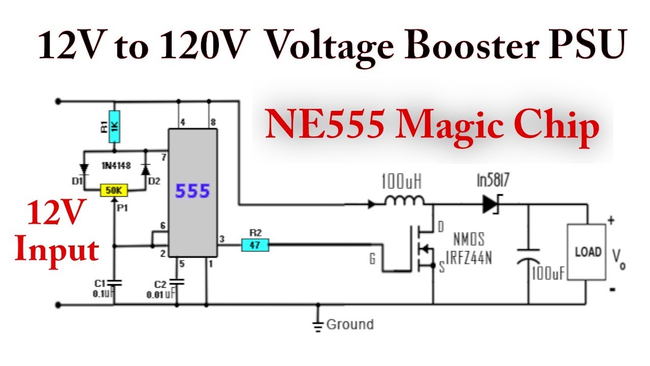
555 DC-DC Boost Converter Power Supply | 12V to 120V - YouTube
