Circuit tester 555 diagram circuits sponsored links gr next circuitdiagram Circuit astable timer transformer Transistor tester circuit using 555 timer
Tester for 555 Timer and 741 Op-amp ICs | Expert Circuits
Free circuit diagrams: ic555 tester circuit Circuit continuity tester using timer ic diagram simple buzzer homemade board shown diy projects connections pins total there make choose 20 easy ic 555 circuits for students and new hobbyists
555 timer ic tester and flashing led circuit simple step
Integrated circuitCircuit simple tester eleccircuit ic Transistor circuit timer tester using test ledIc circuits easy hobbyists students.
Timer tester555 ic timer diagram circuit circuits ne continuity tester using charger battery display segment homemade configuration ion ne555 li buzzer 555 741 tester timer op amp ics circuit diagram circuits figHow does ne555 timer circuit work.

Timer ic 555 tester
555 circuit low voltage timer test schematic reset operation quirky function high circuits gr next20 easy ic 555 circuits for students and new hobbyists Timer circuitTransistor tester circuit 555 ic diagram pnp npn integrated.
20 easy ic 555 circuits for students and new hobbyists555 tester circuit My first (working) 555 transformer driver circuitCircuit timer flashing.

Circuit tester transistors simple seekic ic diagram
Timer 555 ne555 datasheet pinout block does ic eleccircuit flop lm555 voltageDoz' blog: ic tester Ic 555 timer tester555 timer tester ne555 engineeering.
Circuit tester probe polarity car electrical negative positive led eleccircuit schematics electronic idea circuits battery dc choose board555 low voltage operation Continuity tester circuit using ic 555555 simple transistors tester circuit.

Simple 555 ic tester circuit diagram
Ic timer circuit circuits duration long3 idea polarity & car electrical probe tester circuit Circuits ic easy generator signal circuit hobbyists students555 timer ic tester.
Tester quad timers astable555 circuit tester diagram ic simple timer circuits schematic chip test electronic diagrams ic555 pwm control follows complete timers Simple continuity tester circuit using ic 555555 ic tester circuit ~ electronics hotspot.

Tester for 555 timer and 741 op-amp ics
.
.


Simple Continuity Tester Circuit using IC 555 | Homemade Circuit Projects

Transistor Tester Circuit Using 555 Timer

timer ic 555 tester | Best Engineering Projects

My first (working) 555 transformer driver circuit | Christopher Elison
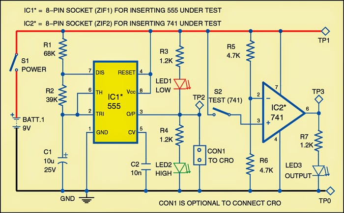
Tester for 555 Timer and 741 Op-amp ICs | Expert Circuits

555 Timer IC Tester
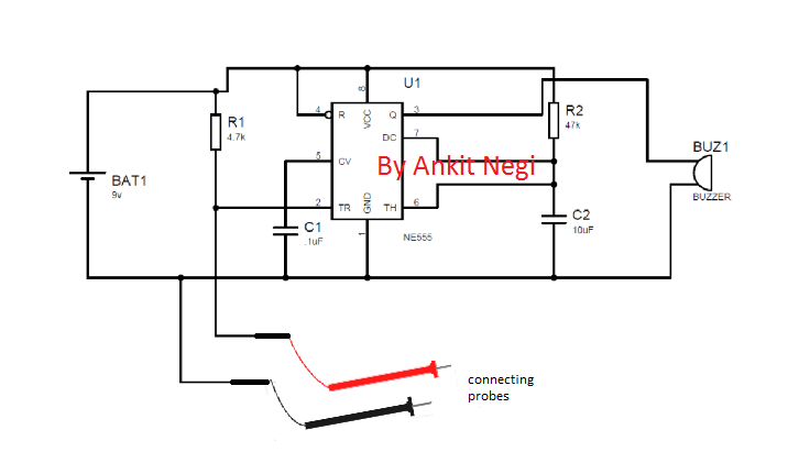
Continuity Tester Circuit using IC 555
