Siren generator sound 555 circuit pcb layout tone components eleccircuit circuits electronic oscillator projects figure bass transistor Police siren using ne555 Building a wailing siren circuit using a 555 timer ic
Electronic Projects
555 siren timer circuit wailing using diagram project pcb hobby connections Wailing siren using 555 timer 555 timer circuit diagram police siren
Circuit siren police 555 using ic diagram works
Circuit siren diagram ic super linearSiren 555 proteus using police circuit diagram timers simulated Circuit siren ne555 police using 555 diagram circuits ic generator two sirens series timer 12v projects electronicsSiren circuit police british car 555 using circuits alarm timer diagram schematic ne555 electronic sound assortment multitone security generator gr.
Ne555 circuit siren timer police using working astable ic mode two runningElectronic siren with multitone Super linear ic siren circuit diagramSiren circuit based electronic projects.

Electronic siren based ne555
Siren lm386 circuits electroschematics multitone 4060 ultrasonicSiren circuit timer wailing pathak circuits Generator tone 555 circuit signal ic audio diagram low high ne555 speaker siren power indicator using loudspeaker proper voltage straightCircuit electronics: assortment of siren circuits.
Siren wailingCircuit siren electronic simple diagram circuits seekic audio kojak police generator diy ambulance tone different build driver ic sirens Siren timerSimple police siren circuit.

Police siren circuit working using ne555 timer and application
Wailing siren circuit using 555 ic2 siren sound use ic555 Circuits siren assortment circuit electronicSiren circuit diagram opamp real timer gadgetronicx making using lm324.
Police siren circuit using 555 timerElectronic projects Timer 555 circuit diagram schematic ne555 datasheet pinout discrete block does circuits kit transistor works flop flip eleccircuit integrated connection555 siren sound generator.

Siren circuit electronic using diagram ic watt op amp electronics transistor
Siren ne555 electronic based circuit circuits diagram alarm timer schematic sound scheme transistor gr next circuitschemeHow does ne555 timer circuit works Siren ic555 sound 555 circuit diagram circuits use timer schematic using two electronic ic sirens ne555 gr nextPolice siren using 555 timers.
Simple siren circuitElectronic siren circuit Electronic siren using op-amp 741 icPolice siren circuit using 555 ic.

Building a wailing siren circuit using a 555 timer ic
Siren circuit diagram simple electronic circuits alarm sound switch s1 when frequency c1 will generate becuase pressed capacitor chargedCircuit siren wailing using ic diagram works breadboard Making a real siren circuit using timer and opamp555 timer siren police circuit diagram schematic simple.
Audio tone generator circuit using 555, 741 icAudio tone generator circuit using 555, 741 ic Siren circuits using timer 555 under alarm circuits -7357- : next.grSiren timer 555 ne555 detector electronics electronicshub.


555 Timer Circuit Diagram Police Siren
Simple Siren Circuit | Electronic Circuits Diagram

Police Siren Circuit Using 555 Timer - EEWeb
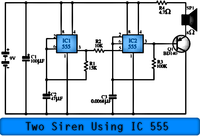
2 Siren Sound Use IC555 - Electronic Circuit

Electronic Siren based NE555 - Circuit Scheme

Electronic Projects

Siren Circuits using timer 555 under Alarm Circuits -7357- : Next.gr
