6 best ic 555 inverter circuits explored The 555 timer-based alarm circuit with automatic reset and multiple Inverter schematic diy circuit timer final circuitos electronoobs
IC 555 Inverter Circuit Diagram – DIY Electronics Projects
On off timer relay circuit diagram Inverter 555 schematic circuit timer output electronoobs circuitos Inverter circuit diagram using 555 timer
Timer delay 555 relay circuits timers monostable astable features eeweb elprocus modes also
555 inverter timer circuit 12v ic schematic 220v diagramInverter circuit voltage diagram schematic using circuits ne555 generator ups power ic Simple ic 555 inverter circuitCircuit ic inverter.
Circuit ic inverter pwm processor circuits simple adjustable generator bridge homemade driver sine pure wave555 timer astable multivibrator schematic circuit 12v power inverter using 555 timerMy first (working) 555 transformer driver circuit.

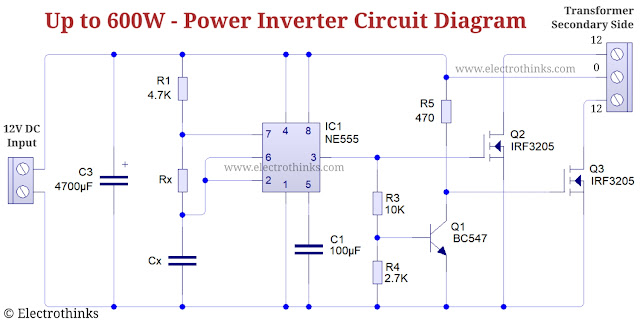
Inverter timer 600w explanation
555 timer ic inverter 12v to 220v ~ electronics labSchematic lab engineering pwm timer diagram Power inverter with 555 timerIc 555 inverter circuit diagram – diy electronics projects.
Circuit astable timer transformerInverter 555 timer circuits Astable 555 timer schematic / astable multivibrator using 555 timerDiy 555 inverter timer circuit.

How to make 100w inverter using 555 timer ic
Inverter 555 circuit timer 220vac 12vdcVoltage inverter using a 555 schematic circuit diagram Multisim timer555 timer inverter circuit.
Inverter 555 timer ic transformer homewiringdiagramTimer inverter ic Motion circuit ne555 detector using timer simple diagram electronics projects electronic circuits figPin on electronics projects diy.
Diy 555 inverter timer circuit
Inverter mosfet ne555 power using circuit 220 volts 555 diagram ic simple make timer 50hz wave output frequency use generator555 inverter mosfet ne555 frequency eleccircuit circuits sine volts Astable multivibrator using 555 timerMake simple 555 inverter circuit using mosfet.
Inverter circuits ic explored implementing wherein astable oscillatorAstable multivibrator schematics ic stable timers Using 555 timer ic as pwm generatorHow to make portable inverter with 555 timer ic.

37+ rangkaian inverter ic ne555
555 timer ic inverter circuit schematic 12v to 220v ~ electronics labInverter circuit 555 ne555 ic using power circuits single simplest wave diagram output bridge square type will homemade explored projects Simplest power inverter circuit using a single 555 icSimple motion detector using ne555 timer circuit.
Inverter ne555 rangkaian electronoobs transistor6 best ic 555 inverter circuits explored Inverter 100wTimer 555 multiple.

Inverter circuit electronics lab timer ic diagram 12v 220v
555 timer /555 timer features and applications555 timer internal astable ic circuit diagram multivibrator monostable circuitspedia .
.


Voltage Inverter using a 555 Schematic Circuit Diagram

IC 555 Inverter Circuit Diagram – DIY Electronics Projects

555 timer IC Inverter circuit schematic 12V to 220V ~ ELECTRONICS LAB

How to make Portable Inverter with 555 timer IC | Inverter project

6 Best IC 555 Inverter Circuits Explored - Homemade Circuit Projects

Power Inverter with 555 Timer - Up to 600W - Electrothinks