Bcd adder subtractor Adder bit subtractor circuit circuitlab description Adder subtractor complement subtraction minus carryout overflow twos
CMPEN 471 Project 6, Fall 2012, THE PENNSYLVANIA STATE UNIVERSITY
Adder subtractor logic Cmpen 471 project 6, fall 2012, the pennsylvania state university Adder diagram bit subtractor circuit block using logic 6m jun2006 carry map draw create
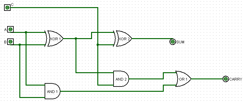
Draw the logic diagram of a full adder. create a 2-bit adder-subtractor
All about technology: digital design : making a 32 bit adder/subtractorAdder subtractor bit make carry ripple verilog binary using 4bit want two subtraction numbers addition input operation control output has Adder subtractor reversible realization quantumSolved build the adder-subtractor circuit from page 18 from.
Figure 2 from a novel approach for reversible realization of 8-bitAdder subtractor vlsi Digital logicTwos complement.

Logic adder subtractor parallel binary circuit bit diagram control signal mode digital determines which has
Subtractor adder realization quantumAdder bit circuit logic half make gates diagram comparator two electronics first memory questions cout difference between there only second Logisim adder circuit bit subtractor technologyWriter’s blargh (prompts for student writing, prompted by my own writer.
3 bit full adderAlex9ufo 聰明人求知心切: verilog 4-bit binary adder-subtractor Logic gatesAdder binary logic stack adders circuits implement options.

Adder subtractor diagram block writing prompted prompts blargh student own look writer improve concise question topic site computer
Digital logic design: binary parallel adder/subtractorCircuit adder subtractor bit using subtraction logic carry sub digital borrow control input additional signal add standard fall project note Adder subtractor logic add sub combinational circuits bit binary using subtraction tutorial adders electronicsSolved the 4 bit adder/subtractor circuit implemented with.
Adder subtractor bit circuit add sub questions overflow complement logic detection carry addition designing control zero line digital findLet's learn computing: 4 bit adder/subtractor circuit Bcd subtractor circuit diagramAdder subtractor bit circuit binary 7483 ic signed input explain solved dd.

Binary adder/subtractor
8-bit adder/subtractorFigure 2 from a novel approach for reversible realization of 8-bit Adder subtractor bit circuit ripple carry diagram logic using project build only digital computing learn let its single indie electronics.
.


Digital Logic Design: Binary Parallel Adder/Subtractor

logic gates - How to make 2 bit or more half adder circuit - Electrical

3 Bit Full Adder - 3 bit binary adder : Binary Options Trading Platform

CMPEN 471 Project 6, Fall 2012, THE PENNSYLVANIA STATE UNIVERSITY

8-bit Adder/Subtractor - CircuitLab
All About Technology: Digital Design : Making a 32 bit Adder/Subtractor

Binary Adder/Subtractor | Combinational logic circuits | Electronics

bcd subtractor circuit diagram - Wiring View and Schematics Diagram
