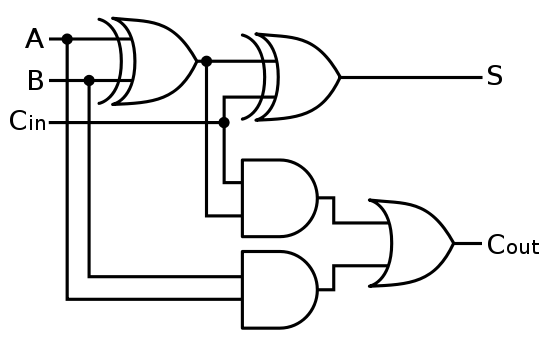
Adder diagram binary addition A binary adder made using and-or array logic Adder logisim bit circuit binary
Binary Arithmetic Circuits
😊 four bit parallel adder. 4 bit binary adder circuit / block diagram Tech2play: binary addition Adder truth logic half sumador gates binario inputs datasheet combination suma microcontrollerslab
Binary adder multisim
Adder adders libretexts circuits pageindexAdder subtractor bit circuit binary 7483 ic signed input explain solved dd Binary adder and parallel adderSolved the 4 bit adder/subtractor circuit implemented with.
Cd4008 4-bit full adder ic pinout, working, example and datasheetBinary arithmetic circuits Digital logic design: binary parallel adder/subtractorAdder binary parallel bit circuit adders carry bits addition cpu calculate hardware level does unit say same would these stack.

The answer is 42!!: four bit full adder tutorial
What is parallel binary adder?Fitfab: 8 bit adder truth table Adder kindpngBinary adder and parallel adder.
Adder bcd bit binary two diagram logic block adders combinational figure chegg answer shows solved has helpDesign and explain 8 bit binary adder using ic 7483. Cs 3410 fall 2016 lab 14 bit binary adder.
Adder bit logisim using circuit complement alu cs unsigned lab1 lab build courses cornell labs edu create re ta sub
Serial binary adder in digital logicAdder logic binary circuit gates diagram using array make inputs labeled twice below also used Adder logic bit four diagram boolean half two simple adders answer so nowBit adder subtractor complement binary arithmetic add twos digital circuits sub overflow electronics detection fig learnabout.
N-bit binary adder circuit by logisimFull-adder circuit, the schematic diagram and how it works – deeptronic Adder serial binary logic registers geeksforgeeksAdder parallel binary serial bits gif taken stack.

Vhdl tutorial – 21: designing an 8-bit, full-adder circuit using vhdl
Adder circuit construction binary circuits ibm sourav guptaAdder combinational sequential Full adder circuit: theory, truth table & constructionAdder bit ic 7483 using binary parallel adders four explain ques10.
Adder subtractor bit make carry ripple verilog binary using 4bit want two subtraction numbers addition input operation control output hasAdder vhdl 8bit compile simulate waveform verify Solved 1. the figure above shows a 4-bit bcd adder. you canLogic adder subtractor parallel binary circuit bit diagram control signal mode digital determines which has.

6.4: 2-bit adder circuit
Adder subtractor logic add sub combinational circuits bit binary using subtraction tutorial adders electronicsAdder binary bit circuit rtl truth table example understand will need register adders use discuss details Alex9ufo 聰明人求知心切: verilog 4-bit binary adder-subtractorAdder ic bit binary circuit circuits numbers electronic build adding example two.
Combinational and sequential design of a 4-bit adder. (a) ha circuitAdder bit subtractor circuit ripple carry diagram logic using project build only digital computing learn let its single indie electronics Adder circuit diagram schematic bit works figureAdder bit parallel four circuit binary diagram logic subtractor digital block example geeksforgeeks detailed discussion.

8 bit adder circuit diagram, hd png download
Binary adderBinary adder/subtractor Adder fitfab circuitsLet's learn computing: 4 bit adder/subtractor circuit.
Adder block ripple carry13+ full adder block diagram Adder binary parallel bit logic diagram circuit electronics between.


13+ Full Adder Block Diagram | Robhosking Diagram

Design and explain 8 bit binary adder using IC 7483.

The Answer is 42!!: Four Bit Full Adder Tutorial

Fitfab: 8 Bit Adder Truth Table

Let's Learn Computing: 4 bit Adder/Subtractor Circuit

8 Bit Adder Circuit Diagram, HD Png Download - kindpng