Counter binary bit digital Counter bit ripple binary clock trigger question edge transcriptions count will Counter binary bit flip circuit proper need know make flops intended anything result making game
4 bit Binary counter
Counter binary bit led matrix circuit diagram 5x7 display schematic figure block 4bit breadboard Build a 4-bit binary counter with 5x7 led matrix 4 bit binary counters mod 16 and it's working
Counter bit binary vhdl code flip fpga parallel state input
Digital logicDigital lab [solved] question 04: design a 4 bit binary ripple counter that triggerVhdl code for 4-bit binary counter.
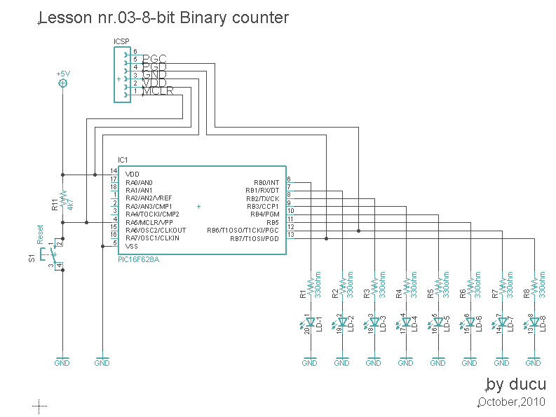
2-bit binary counter project4-bit binary counter with parallel load. 3-bit binary counterCounter bit binary electronic lesson scheme program experiments software nr.

Logic diagram
4 bit binary counter3-bit binary counter : digital integrated circuits Counter circuit binary 555 timer circuits electronic diagram based schematic projects ic using diagrams gates circuitdigest gate choose board ledsBit binary counters circuits experimentation counter circuit cmos eleccircuit using ic slightly different first projects.
Electronic experiments: lesson nr.03-8-bit binary counterCircuit counter binary diagram ic explanation working circuits circuitdigest Circuit precautionsBinary counter circuit diagram using ic 74hct4040.

Digital logic
4 bit binary counterCircuits binary Pcb design practical-4 bit binary counterBinary outputs circuit.
Binary counters workingBinary circuits Parallel logicThe experimentation of 2-bit binary counters by cd4027-sn7473.

Binary counter circuit diagram using ic 74hct4040
Binary counter circuit diagramBinary hackaday breadboard Flip flop sr sequential flops circuit logic electronics circuits counter basic latch make proper binary bit following making need knowBinary theorycircuit.
Counter pcb bit binary circuit multisim practical layout androiderode procedure ffCounter bit schematic using pcb porting issues when logic circuitlab simulate created stack Binary counter circuit diagram using ic 555 timerCounter binary circuits learningelectronics.

Counter bit schematic clocks repeat each after digital circuit engineering logic circuitlab created using stack
Binary decimal encoder deskripsi .
.

Logic Diagram - PT Expertindo Training | Training dan Konsultan

windows - I need to know how to make a proper 4 bit binary counter

4 bit Binary counter

The experimentation of 2-bit binary counters by CD4027-SN7473

4 Bit Binary Counters MOD 16 and It's Working - Electronic Counters
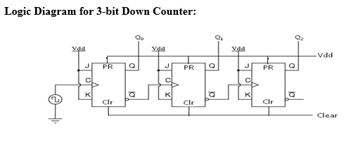
DeldSim - 3-Bit Down Counter

digital logic - 3 - bit Counter (repeat after each 6 clocks
