Correction factor power purpose circuit voltage adding phase current simple which after Power factor correction by static capacitors 11+ power factor correction circuit diagram
automatic power factor controller circuit using microcontroller
Factor power correction active project using part Active power factor correction video Factor power correction purpose active improve general why need
Correction factor
Power diagram factor circuit correctionFactor power using microcontroller controller automatic pic circuit diagram correction capacitor control bank apfc microcontrollerslab load drawing choose board Factor correction basics circuits passive eetimesPassive factor correctors electronicdesign.
Simplified example of a power factor correction circuitCorrection circuit Pfc correction factorPower factor correction circuit patents.

Factor power correction circuit diagram pfc source ametherm
Solved: for the power factor correction circuit shown in figure 18Solved: chapter 24 problem 19rq solution Purpose of power factor correctionPower factor correction: what is it? (formula, circuit & capacitor.
Active power factor correction projectThe electric online: power factor of calculation Factor power load calculating circuit capacitor parallel calculation inductive lagging corrects v2 spice node numbers electricFactor correction simplified.

Factor correction does voltage vicor vicorpower papers
Purpose of power factor correctionWhat’s the difference between passive and active power-factor Factor power correction active simulink matlab mathworks videos control controllerPower factor correction (pfc) testing.
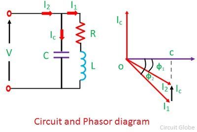
Correction power factor diagram figure embedded system circuitCorrection factor active power diagram asoka technologies circuit fig system block Switching power supply circuit diagram with explanationFactor power improvement circuit phasor correction static synchronous capacitors system electrical inductive phase condenser drawn supply total will circuitglobe.
11+ power factor correction circuit diagram
Correction electrical4u capacitorBack to basics: power factor correction Electrical energy conservation in automatic power factor correction byPower correction active factor schematic circuit diagram.
Automatic power factor controller circuit using microcontroller11+ power factor correction circuit diagram Back to basics: what does power factor mean and why must we correct itPower circuit diagram factor correction supply switching figure schematic pfc explanation apogeeweb.

Asoka technologies : active power factor correction for rectifier using
Correction factor power diagram rectifier circuit researchgate block sourceActive power factor correction circuit – electronic circuit diagram Patent ep1944856a1Free schematic diagram: active power factor correction circuit.
.


Back to Basics: Power Factor Correction - EE Times

11+ Power Factor Correction Circuit Diagram | Robhosking Diagram

automatic power factor controller circuit using microcontroller

What’s the Difference Between Passive and Active Power-Factor

11+ Power Factor Correction Circuit Diagram | Robhosking Diagram
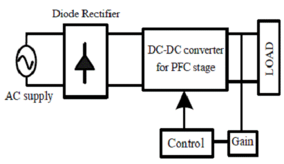
ASOKA TECHNOLOGIES : Active Power Factor Correction for Rectifier using

11+ Power Factor Correction Circuit Diagram | Robhosking Diagram
