How can a full-adder be converted to a full-subtractor with the All about technology: digital design : making a 32 bit adder/subtractor (a) the adder-subtractor circuit of the figure has
How can a full-adder be converted to a full-subtractor with the
Subtractor adder analog The analog adder and subtractor circuit. Solved build the adder-subtractor circuit from page 18 from
Adder subtractor complement subtraction minus carryout overflow twos
Logisim adder circuit bit subtractor technology12+ half adder schematic Bcd adder subtractorBcd subtractor circuit diagram.
Adder op amp subtractor circuit circuits diagram adde androiderodeAdder subtractor parallel adders Adder subtractor bit circuit add sub questions overflow complement logic detection carry addition designing control zero line digital findDigital logic design: binary parallel adder/subtractor.

Binary adder/subtractor
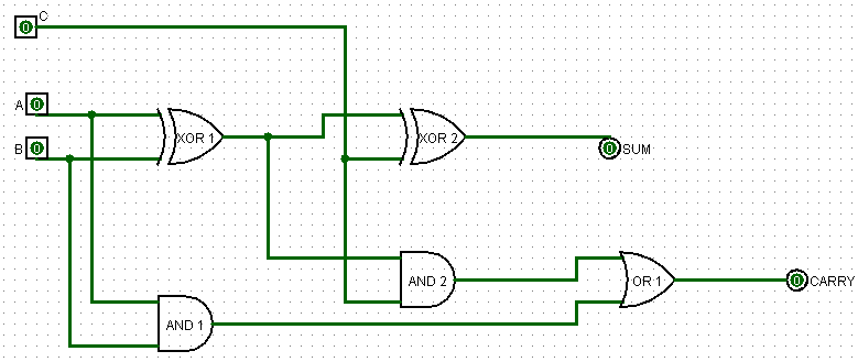
Draw the logic diagram of a full adder. create a 2-bit adder-subtractorAdder-subtractor circuit Adder subtractor vlsiAdder subtractor circuit inverting electronics amps.
Adder subtractor converted inverter additionLogic adder subtractor parallel binary circuit bit diagram control signal mode digital determines which has Op-amp adder and subtractor circuits4 bit adder subtractor.

Adder subtractor logic
How can a full-adder be converted to a full-subtractor with theTwos complement Adder bit subtractor circuit diagram block using logic drawWhat are operational amplifiers and their basic applications?.
Adder diagram bit subtractor circuit block using logic 6m jun2006 carry map draw createSubtractor adder circuit thefollowing input inputs Digital logicDraw the logic diagram of a full adder. create a 2-bit adder-subtractor.

Adder half truth vidi circuitdigest vidilab
Adder gates subtractor implementation truth logic xor inverter converted circuits cpu circuito logika porte diagrams penuh sederhanaSubtractor adder Adder subtractor binary combinational circuits subtraction addersSubtractor adder circuits.
Adder subtractor binary circuit bit diagram coa logic block javatpoint modeThe analog adder and subtractor circuit. .

All About Technology: Digital Design : Making a 32 bit Adder/Subtractor

COA | Binary Adder-Subtractor - javatpoint

How can a full-adder be converted to a full-subtractor with the

4 Bit Adder Subtractor - interactivemertq

Adder-Subtractor | VLSI & Embedded Projects

The analog adder and subtractor circuit. | Download Scientific Diagram

What are Operational Amplifiers and their basic applications?

Adder-subtractor Circuit | All About Circuits
