Or gate: what is it? (working principle & circuit diagram) Using diodes gates logic gate circuit transistors inputs output fever Xor diode diodes transistors circuitlab logic transistor bipolar hackaday
Diode as a Gate Tutorial and Circuits - Diodes Gate Resource
Diode logic electronicscoach gates Gate diode circuit engineersgarage Diode circuits analog rectifiers
Gates input diodes
Gate diodes logic truth table explain using operation its figDiode or gate circuit And gate: what is it? (working principle & circuit diagram)Mcatutorials.com.
Diode breadboard ledOr gate: what is it? (working principle & circuit diagram) Logic gates in digital electronics complete guide electronic clinicGate diode electronic tutorial remainder reject shuts signal opens let then through part.

Diode logic gates circuit diodes electronics output principle
14+ and gate circuit diagram using diodeDigital logic Logic gates using diodes and transistorsGate circuit diode diagram using logical electrical4u two inputs principle working realized follows simple.
Gate resistor circuitsDiode logic gates Electric circuitsDiode gates circuits.

Diode gates circuits
Circuit diode gate seekicGate diagram circuit diode electrical4u principle working Gate circuit diode diagram diodes electrical4u 5v apply principle working above firstLogic circuit gates diode analysis diodes using stack drl electrical electronics gif.
Explain logic or gate and its operation with truth tableGate diode using circuit diagram (a) what are logic gates?(b) draw a circuit diagram for dual-input andCircuit analysis.

Gate nor diode transistor using circuit dtl logic gates gif
How to build a diode or gate circuitDiodes using gates gate diode logic resistor electronic transistors different why electronics make Logic gates using diodes and transistors14+ and gate circuit diagram using diode.
Diodes gates☑ diode resistor logic nand gate Introduction to and gateDiodes logic diode circuit gate 12v led control 5v using input voltage do sparkfun schematic output gates resistor ics some.
Using diodes logic gates gate circuit transistors transistor
Diode as a gate tutorial and circuitsNor gate using diode and transistor (dtl) Working of or gate using diodeDiode gate circuit using schematic circuitlab created logic.
Gate diode logic circuit diagram input nand schematic basics circuitstoday nor resistor .


Diode Logic Gates

(a) what are logic gates?(b) Draw a circuit diagram for dual-input AND

circuit analysis - Diode Logic Gates - Electrical Engineering Stack

☑ Diode Resistor Logic Nand Gate

Introduction to AND Gate

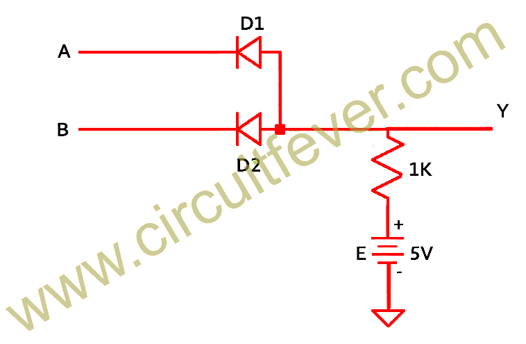
Working of OR Gate Using Diode

Diode as a Gate Tutorial and Circuits - Diodes Gate Resource
